1. Light and Radiation
Spectral analysis: Beamsplitters (2/2)
Spectrometers which are used for airborne remote sensing can be realised with dichroic beamsplitters and filters as well. An example of this is the spectrograph of the LFS, an airborne fluorescence lidar, as shown in the following illustration. With this instrument, an object of interest is illuminated with laser beams causing an emission of fluorescence light which is then measured at a number of wavelengths. This method is applicable for analysing vegetation on land and algae in the ocean, detecting oil and other types of pollution, as well as other areas of environmental monitoring. More detailed information can be obtained in the SEOS tutorial on Remote Sensing Using Lasers.
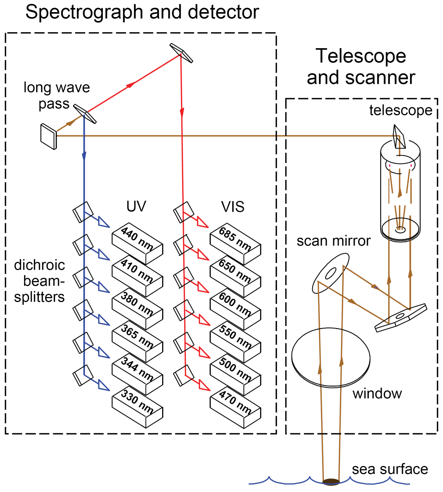
A scanner is used to provide two-dimensional data from the sea surface. The laser-induced fluorescence is collected with a telescope and fed to a dichroic long pass filter. This filter reflects radiation at wavelengths below 450 nm and transmits higher wavelengths. Each of the two partial beams then pass six dichroic beamsplitters which reflect the wavelengths of interest and transmit smaller wavelengths. The partial beams are then spectrally defined with interference filters. Photodetectors provide electric signals for further data processing.