Supplement 1.10: Radiation detectors (2/5)
Quantum detectors (1/4)
Thermal detectors measure the heat generated by the absorption of radiation. The radiation can be thought of as an electromagnetic wave or as photons. In the case of quantum detectors, the measurement process cannot be explained using the electromagnetic wave model. Classical physics had already failed in the case of thermal radiation. The solution to this dilemma can be traced back to Max Planck, who successfully introduced the photon model in 1900 to explain temperature radiation. On this basis, Albert Einstein was able to interpret the photoelectric effect, the emission of electrons from irradiated metal surfaces, in 1905, which had also been incomprehensible until then. Detectors whose function is based on the photoelectric effect are therefore quantum detectors. These include vacuum photodiodes, which are no longer in use, photomultipliers (or photoelectric multipliers), semiconductor photodiodes, phototransistors, and avalanche photodiodes.
Vacuum photodiodes
These detectors, also known as vacuum photocells, consist of a photocathode and an anode arranged in an evacuated glass tube. The electrons released from the photocathode by radiation are accelerated to the anode by an externally applied voltage of approx. 10 to 100 V and absorbed by the anode. This is known as the photocurrent. It should not exceed approximately 10 µA, as otherwise the proportionality between the photocurrent and the irradiance, i.e. the linearity of the detector, may be lost.

Even in the dark, a very small current of about 0.1 to 1 nA flows, which is called dark current. It is caused by electrons whose energy is significantly greater than the average kinetic energy E≈kT and greater than the work function of the cathode, and which therefore pass from the cathode into the vacuum; k=1.38·10-23 J/K is the Boltzmann constant and T is the absolute temperature. The work function can also be described as the binding energy of the electrons in the cathode; it must be overcome in order to release electrons into the vacuum. The thermally induced dark current can be significantly reduced by cooling the photodiode if very low brightness levels are to be measured.
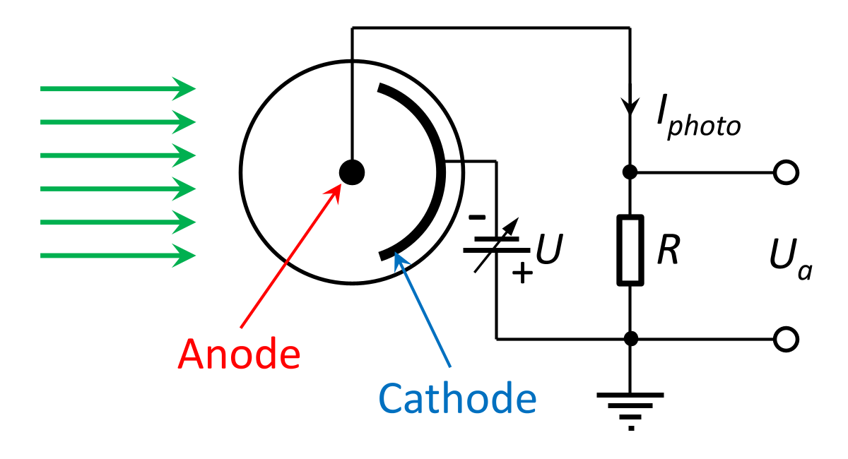
The diagram on the right shows the circuitry of a photodiode. A voltage U, which can be adjusted in height, ensures that the electrons released from the cathode by the light (green arrows) are accelerated towards the anode. The photocurrent Iphoto flowing through the resistor R generates a negative output voltage Ua=-R·Iphoto. The direction arrow on Iphoto indicates the direction of the electron current, which is opposite to the technical direction of current. Instead of the resistor, an ammeter with a measuring range below 1 µA can also be used.
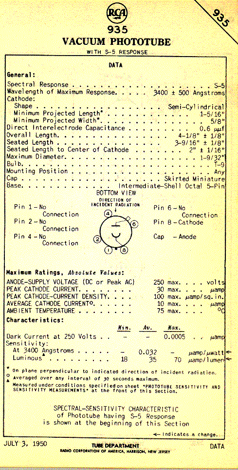
The voltage U can be several volts and, for the RCA 935, may be increased to a maximum of 250 V. High voltages result in very short electron transit times (i.e. the time taken for electrons to travel from the cathode to the anode) of around 3 ns. The transit between the cathode and anode then also exhibits reduced temporal dispersion, which improves performance at high frequencies.
However, measuring short pulses in the nanosecond range remains difficult due to the parasitic capacitances of the cathode and anode, which amount to . This would require a small resistance commonly used in high-frequency technology to achieve high cut-off frequencies . However, the signal voltage Ua then remains very small. This disadvantage is overcome by the photomultiplier presented in the next section.
For measuring slowly varying light signals, resistors in the range R=1 - 10 kΩ are suitable for achieving signal voltages that can be easily measured. One disadvantage that arises with large values of R is that the signal voltage may become too high. If Ua approaches the cathode voltage U the photoelectrons lack the acceleration voltage and their transition to the anode is impaired. This effect can be prevented by using an additional amplifier, as shown in the diagram below.
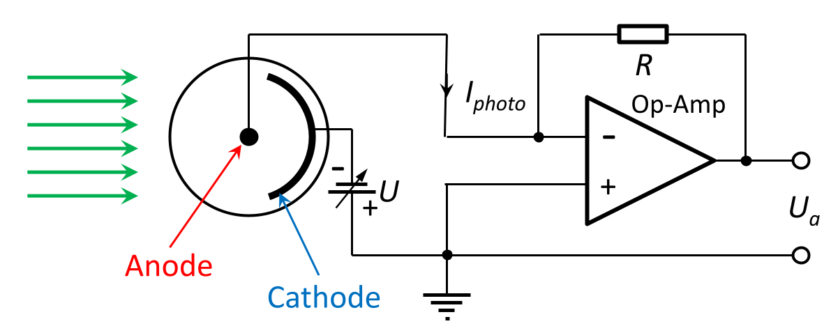
The function of the operational amplifier (OP) is to minimise the voltage difference between its inverting (-) and non-inverting (+) inputs. It therefore regulates the potential at the inverting input to zero. To achieve this, it generates an output voltage Ua which results in a current flowing through the resistor R such that the sum of the currents at the inverting input is zero (Kirchhoff’s node rule). The current through R is therefore equal to -Iphoto, and the voltage between the cathode and anode, i.e. the acceleration voltage of the photoelectrons, remains unchanged. Due to the use of the inverting input, the output voltage has the opposite sign compared to the simpler circuit shown above without an OP.
