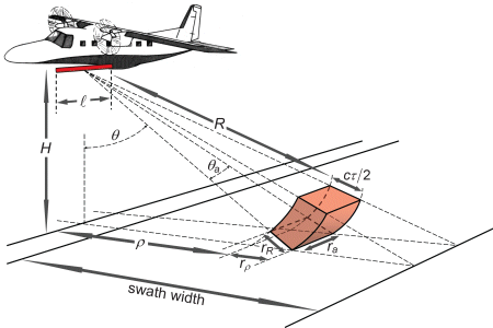
Principle of operation

Geometry of SLAR operation and resolved surface area. The SLAR antenna (shown in red colour) with length
is mounted to the lower side of the aircraft at flight altitude H. A section of the beam emitted at nadir angle
θ is considered. The element shown in red colour denotes an irradiated volume at distance R.
Other parameters are explained in the text.
Another parameter of radar instruments is the polarisation of emitted radar pulses and received signals.
Due to the linear shape and along-track alignment of the SLAR antenna, electromagnetic waves are emitted
with the electric field vector in a vertical orientation with respect to the plane of incidence to the ground.
In the same way, backscattered waves are registered with the same orientation of the electric field vector.
These characteristics are referred to as VV polarisation, i.e., vertical for both the emitted and received
waves. With other instruments, e.g., radar in space, a HH polarisation (horizontal-horizontal)
and a HV or VH polarisation (i.e., cross-polarisation of the emitted and received waves) can be used for
specific applications.
Équations ↓ ↑
Les équations mathématiques sont présentées en utilisant le
Mathematical
Markup Language (MathML), qui est pris en charge par Mozilla Firefox
et Safari. Il peut ne pas être disponible pour d'autres navigateurs.
The pixel dimensions are functions of the beamwidth in the along-track direction and the pulse length in the
slant range direction. For the beamwidth angle θa it follows from the principles
of diffraction of electromagnetic waves:
where λ is the radar wavelength and
is the antenna length.
Synthetic antennas ↓ ↑
Obviously the antenna length
is a crucial parameter for the beamwidth angle θa which - as we will see below -
determines the ground resolution: a larger antenna decreases the beamwidth angle. This is especially important
when using radar instruments on satellites, because of the much higher distance to the ground which
would otherwise lead to a very poor ground resolution.
This drawback can be reduced by synthetically increasing
the antenna size up to the required length, which is possible due to the coherence properties of the radar signals.
Suppose an object which is hit by several pulses one after the other emitted and received by the aircraft or
satellite during overflight. If the received signals are stored then the signals can be treated as if they were
simultaneaously emitted and received by an antenna having a length of the flight track between the first and the
last pulse. This makes it possible to resolve objects on the ground with an along track size which is at least
as large as the synthetically enlarged antenna length.
These radar instruments are called Synthetic Aperture Radar or SAR.
A detailed description is given in a separate chapter on satellite SAR.
Radar Instruments using the antenna as is are called Real Aperture Radar or
RAR. The Side-looking Airborne Radar (SLAR) used in maritime surveillance is a RAR.
The along-track resolution is then:
The along-track resolution is therefore a function of the slant range R and is not the same
in different parts of the image.
The slant range resolution is:
where τ is the radar pulse length, c is the velocity of light,
and θ is the nadir angle of the considered radar pulse section. The factor
of two in the denominator is due to the fact that the radiation propagates forth and back the
distance interval rR to achieve this resolution. The horizontal resolution
on the ground is then:
The pixel dimensions ra and rρ depend on
the angle of incidence θ and hence on the distance to the target
sidewise of the flight track.
Exercise: Radar pixel size
↓ ↑
We perform a surveillance flight over coastal waters. The SLAR has the following characteristics:
- antenna length: 3 m
- microwave frequency: 10 GHz
- pulse length: 50 ns
- horizontal beamwidth angle: 0.5°
The aircraft is operated at 1000 m flight altitude. At a horizontal distance of 5 km sidewise
of the flight track we can see a target in our radar image. Could this target be as small as
a floating barrel having 1 m size, or will it be more likely a lost 30ft. container or even
a 50 m long ship?

